Radar Level Transmitter – EIP 140 GHz
EIP Enviro Level Controls Pvt Ltd introduces the 140 GHz Radar Level Transmitter, the world’s highest operating frequency for radar level measurement. This advanced solution ensures unparalleled precision, sensitivity, and stability, making it ideal for high-demand industrial applications.
The ULM level sensor is installed on the roof of the tank
EIP 140 GHz Radar Level Transmitter is the world’s highest operating frequency for a radar level transmitter.
EIP’s 140 GHz Radar series are built on the operating principle of a chirp radar; this principle is better known in foreign transcription – FMCW (we will use this abbreviation in the article).
Operating principle
The continuous principle (FMCW) is most optimal for high-precision measurements and level measurements in conditions of weak reflections; it can significantly improve the quality of level measurements, increase the accuracy of level measurements, minimise the influence of parasitic interference and interference associated with unevenness (unrest) of the surface of the measured product, and increase the stability of measurements compared to other methods (pulse).
How it works?
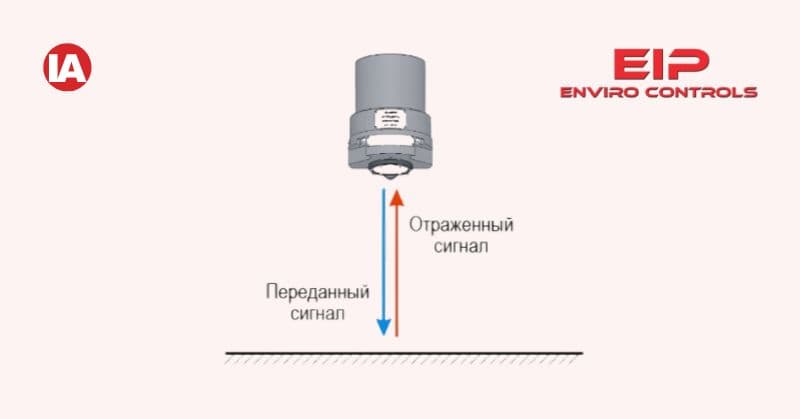
The ULM level sensor is installed on the roof of the tank. The microwave generator of the level sensor (Fig. 1) generates a radio signal, the frequency of which varies over time according to the linear law of Fig. 2 (linear frequency-modulated signal). This signal is emitted in the direction of the product, reflected from it and part of the signal, after a certain time depending on the speed of light, returns back to the antenna.
The difference in frequency of the transmitted and reflected signal f1 (Fig. 2) is proportional to the propagation time of the electromagnetic wave t1 to the product and back. Knowing that the speed of wave propagation is equal to the speed of light and knowing the propagation time, you can easily calculate the distance from the antenna to the product (reflector).

But this is an ideal case, possible only with an ideal reflector. In reality, there may be foreign structures in the tank, there may be disturbances on the surface of the product, the surface of the product may not be smooth (loose product), etc. In this case, the pattern of the reflected signal may be completely different (Fig. 3).

In this case, it is impossible to determine the frequency difference by simple subtraction – there is no single value. Therefore, a more complex operation of mixing the emitted and received signal is used. The result is not a number, but a low-frequency resulting ‘signal’ in which both useful and spurious frequencies are present.

Further processing of the signal is carried out by the microprocessor system of the level sensor and consists of accurately determining the frequency of the useful signal and recalculating its value into the value of the tank filling level.
To do this, the resulting signal obtained as a result of mixing the transmitted and received signal is subjected to spectral analysis. Using digital processing methods, the frequency signal is converted into a spectral pattern.

Measuring beam width
One of the main characteristics of any Radar Level Transmitter, affecting most of the operational characteristics (measurement accuracy, measurement stability, sensitivity), is the width of the measuring beam.
High sensitivity
A level sensor installed on the roof of the tank emits electromagnetic waves towards the controlled product – a measuring beam having an expanding radiation pattern.
The existence of such a radiation structure is associated with fundamental physical laws. As an analogy, we can cite an electric flashlight in which the light spot will be larger, the further the illuminated surface is located from it and the smaller the diameter of the reflector (‘antenna’) of the flashlight. And we see this spot of light only because the light is reflected and hits our eyes (the ‘receiver’). A very similar principle applies to electromagnetic waves in the microwave range. An electromagnetic wave is emitted towards the product, reflected from it and returned to the antenna of the level sensor.
The width of the measuring beam is characterised by the beam divergence angle. And the wider the beam (the greater the divergence angle), the smaller the percentage of the emitted signal (other things being equal), after reflection, will return back to the receiver of the level sensor and ‘bring’ information about the filling level of the tank. The narrower the measuring beam of the level gauge, the more sensitive the level gauge. Therefore, a narrower beam can significantly improve the quality of level measurement, and this effect is more noticeable and the more it improves the quality of the level gauge, the higher the installation height (i.e., the higher the tank). The width of the measuring beam of the ULM-11 level gauge is 1-2°.

Convenience of placement
The narrower the beam, the easier it is to install the level gauge on the tank. The level sensor of the level meter can be placed closer to the tank wall; it is easier to choose an installation location in such a way that the measurement is not interfered with by foreign objects and structural elements of the tank.
The entry of foreign objects and structural elements of the tank into the measuring beam leads to additional interference and, as a result, to an increase in the likelihood of deterioration of the measurement error and the occurrence of situations with unstable measurements.
Thus, a level gauge with a narrower beam may serve as a more versatile level measurement tool than a level gauge with a narrower beam.

Low di-electric
With the principle of measurement of Radar Level Transmitter involving the receipt of a good reflection from the surface (based on the chargeability/di-electric of the medium) where the surface atoms are charged and when they get back to a stable state release an equivalent energy back as reflection. Hence having a higher frequency of 140 GHz having more power coupled with a very small beam angle of less than 2 degrees allows a very high power to be transmitted to the surface of the material and hence ensures charging of the surface atoms and a good reflection back to the Radar. (Below figures are representative of the above explanation).
Hi-tech
The beam width can be reduced by increasing the diameter of the level sensor antenna and increasing the frequency of the emitted electromagnetic signal. For example, the ULM-11 level transmitter operates at a frequency of 140 GHz and, with an antenna diameter of 86 mm, has a measuring beam width of 1-2°.
The ULM range of level gauges has various modifications of level gauges, with different metrological and operational characteristics. Therefore, for most level measurement tasks, you can choose the most optimal solution in terms of price/quality ratio.
How to leverage the 140 GHz solution
To get your application problem solved, please connect with a representative from EIP Enviro Level Controls Pvt Ltd, Noida at Email: [email protected] or Contact +91-9818953439/9818953473.

"This article presents EIP’s 140 GHz Radar Level Transmitter, the world’s highest-frequency radar for level measurement, delivering extreme precision, narrow beam width (~2°), and reliable performance in harsh industries. EIP is a leader in industrial instrumentation, solving real measurement challenges—dust, interference, and uneven surfaces—with cutting-edge radar technology."